Making A Howe Truss Bridge
We started with the trestle bents, assembled those into a set of approach trestles, then set the bridge in place. Well, there's a lot more to it than that. We actually started with smaller sections and shorter trusses. The progressed into longer and taller trusses, two at a time, one for each side. Sounds simple, right?
Wrong! Our original approach was sectional, based on a kit design we found online, meant to ease shipping. It's far easier and cheaper to ship an assortment of parts in a reasonably shaped shipping container than to ship an assembled bridge in a long, skinny form factor, not to mention the increased risk of damage in transit for an oddball shaped package.
That being said, it seems reasonable to use that approach for building our bridge(s). So the way it works is the bridge trusses are assembled in sections. There are two end sections, roughly 6" in length, and a center span of the length required to yield the desired overall length of the bridge in 3" increments. It's difficult to describe, but parts overlap in progressively longer or shorter segments so each section can overlap.


The parts are all interchangeable for each successive size. Imagine a rectangle, about 3" x 5", with just the top and bottom, connected by an "X" of crossmembers. Now imagine the top and bottom members are stacked, three tall, with the ends of the two crossmembers sandwiched between them. The first layer top and bottom are 9" long with three crossmembers stacked on top, all leaning the same direction.
The next stack of tops and bottoms is only 6" long, aligned to the left edge of the bottom layer. But this time with only one crossmember, at the opposite angle of the first three, also aligned to the left edge. For the top layer, the tops and bottoms are only 3" long, again aligned with the left edge. Make two of them at the same time. Now flip one over so that the 3" members are on the bottom and align that with the other's 9" section.
Presto! We now have an entire 12" truss! Want it longer? Make a center section in the same fashion in the additional length desired. All the tops and bottoms need to be that additional length, each staggered by 3". Now build that center section in place over the left end, stacking the crossmembers and next layers to match. Once it's done, take that flipped over right end and put it in place. We now have a bridge truss the desired length!


The original template was less that adequate. The "next gen" was made using a dado head in the table saw and a suitable miter gauge to cut the recesses in the ¾" plywood at the proper angles. Of course mistakes were made, and the slots had to be cut twice to get them deep enough and in the correct position. The original cuts weren't deep enough for the top and bottom members to nest enough for the crossmembers to engage.
But even the new template fell short when trying to assemble the truss spans. It was only good for the first two layers (out of five). After that, everything was just precariously placed, waiting to be fastened together with the remaining parts. By the end, making the howe truss bridge turned into a major production, including specialized templates for the dremel drill press to make more consistent bores for the fasteners.
All that aside, the one lesson learned is the segmented approach may work well for selling and shipping kits, but it leaves much to be desired for easily assembling a sturdy bridge. The problem is the number of components that need to come together at every joint, or rather, the juggling of all those components while attempting to fasten them together at that joint.


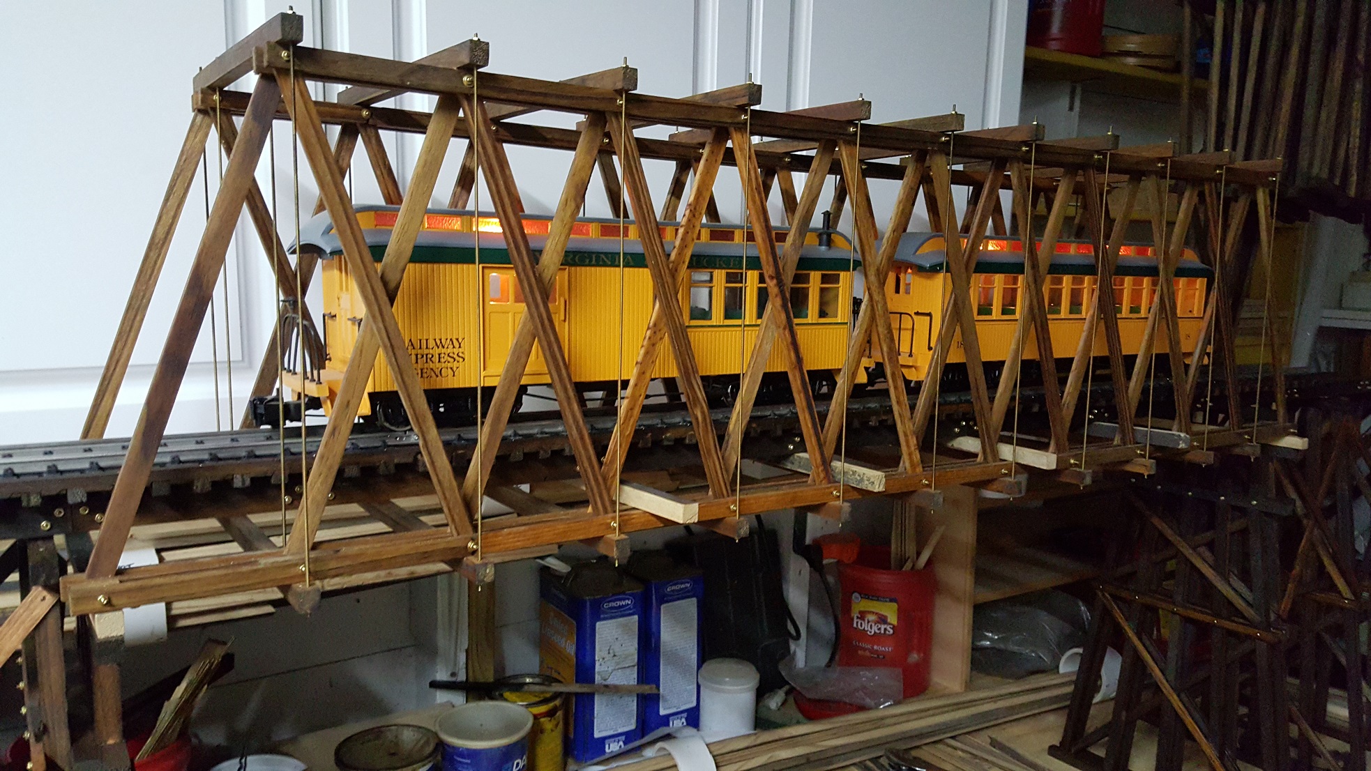
Beyond assembling the truss spans, assembling two truss spans into a single bridge pointed out the flaw in the segmented truss design. Well, the first issue is how to hold everything in place while "strapping" the two trusses together with the upper and lower beams and tightening the "tension rods". It's one of those "need three hands" situations for sure.
Preassembling the the beams and tension rods allows them to be slid over the two truss spans, as a unit, to the center joints in the trusses. Tightening the tension rods on either side just enough holds the trusses in place while adding more and more of them until complete. This is when the flaw in the design appeared. The more the tension is increased, the more every segmented joint in the truss wants to separate and come apart!
Turns out using a single length for the top segments and a single length for the bottom segments for the entire length of the truss is best for its strength and stability. A solid piece of wood isn't going to separate, short of applying enough force to snap it into pieces. While it's not back to the drawing board, it does mean all that work to assemble those trusses needs undone, and all those separate pieces replaced with strong, single length members. Live and learn.
That's the reason for the dremel drill press templates, the need for evenly spaced, repeatably spaced bores for the fasteners to join all the truss members togethe, learning from the shorter "test" span that using hand drilled holes means nothing fits together as closely as it needs to be to keep things straight and true. Unfortunately, that first bridge was already too "compressed" by this to separate when tightening things together.
As an aside, this bridge "design" strays from the prototype, using a more practical approach for modelling. The prototype has metal "joiners", or joint plates, essentially pinned metal spacer blocks that keep everything aligned. The members aren't fastened together at a common joint, but rather rely on the vertical tension rods keeping every member of the truss firmly in compression.
The vertical tension rods pass through the joiners and the top and bottom truss members themselves, not separate beams above and below the trusses. What actually does pass through those bores on the prototype is another set of tension rods, horizontally, separated by the upper and lower members that keep the trusses fastened together, yet spaced apart.
Sometimes those horizontal tension rods actually pass through the center of the truss span between the joint plates, keeping those horizontal crossmembers between the two trusses in compression as well. Another "feature" of the prototype is fastening the shorter members together into one long top and bottom member, the length of the truss using the equivalent of "mending plates", large metal plates that bolt the ends of the two shorter members together.
Pictures, thousands of words, all that... Stay tuned, more to come, including more recent trestle work!